MouseCam: Imaging from an Optical Mouse Sensor
Overview
MouseCam is a project with the goal of extracting live image data from the optical sensor inside a 20-year-old Logitech mouse and streaming it wirelessly to a PC for display. Optical mouse sensors are essentially tiny specialized cameras that capture microscopic images of whatever surface is under the mouse, roughly 1500 times per second, and compute motion by comparing consecutive frames. This project aims to construct image data from the mouse sensor chip by stripping out the mouse's original microcontroller, wiring the sensor chip directly to an ESP32-S3 Mini, and using a custom bit-banged serial protocol to read the raw pixel array out of the sensor. The captured 16x16 pixel frames are then sent over WiFi to a Python viewer on a laptop, which contrast-stretches and upscales them into a live 512x512 display. The end result is a salvaged mouse acting as a miniature wireless camera.
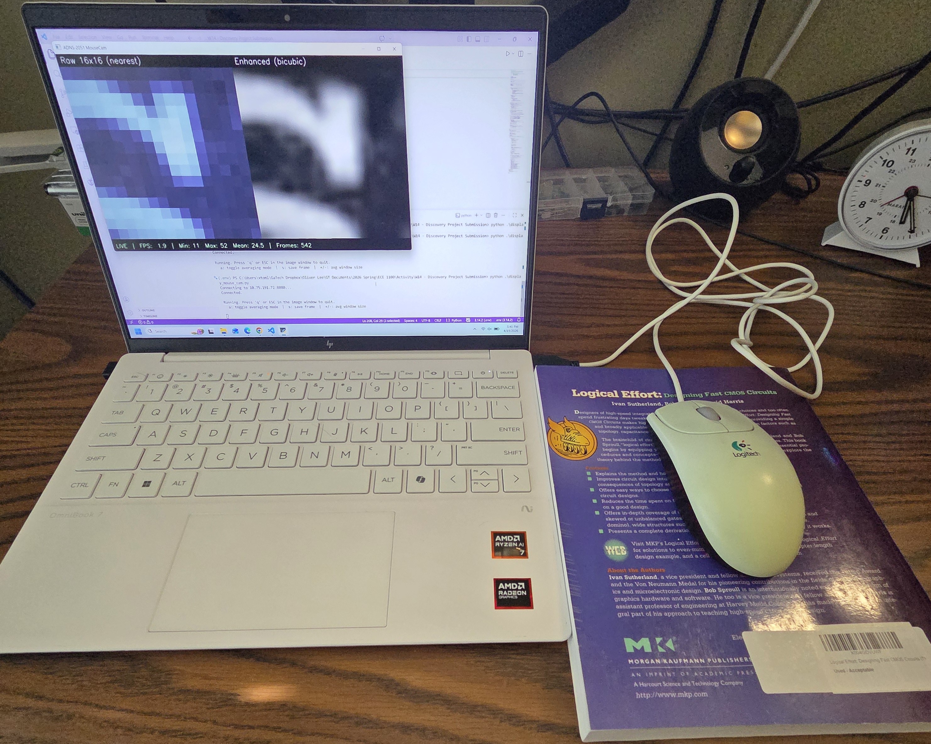
Figure 1. The finished hacked mouse and a live image display of its readings. Note that the USB connection is only for powering the mouse.
Project Idea and Descoping
The original pitch was to build a complete portable camera using the mouse sensor and a proper lens assembly, fitting everything into a small battery-powered package. Along the way, two parts of that scope proved much more involved than anticipated:
- Sourcing and aligning a lens that could actually focus an image onto the tiny 1mm x 1mm sensor window
- Designing a custom enclosure and power system for portable operation.
I also spent time on a dead end early on. Originally, I planned to pull image data through the mouse's proprietary Logitech microcontroller, but after hours of reverse-engineering the mouse PCB, I realized that talking to the sensor chip directly is an easier approach. That effort was not wasted though; what I learned about the mouse's PCB will be useful for designing a custom mouse PCB in a future project.
Given these constraints, I descoped the project to focus on getting pixel data off of the sensor chip itself. This still required reading a dense 20-year-old datasheet, implementing a custom serial protocol from scratch, and building the whole capture and visualization pipeline. The portable-camera reach goal was dropped, but the core discovery, that you can take a discarded mouse and turn it into a live imaging device, was preserved.
The Sensor: ADNS-2051
The mouse used for this project is a Logitech M-BJ58, which contains an Agilent ADNS-2051 optical mouse sensor in a 16-pin staggered DIP package (Figure 2). The datasheet for this chip is from 2003, but it is thorough and well-documented.
Two key features of the ADNS-2051 relevant for this project are:
- It has a 16x16 pixel array with a pixel depth of 6 bits.
- A single bi-directional serial port for register read and write access.
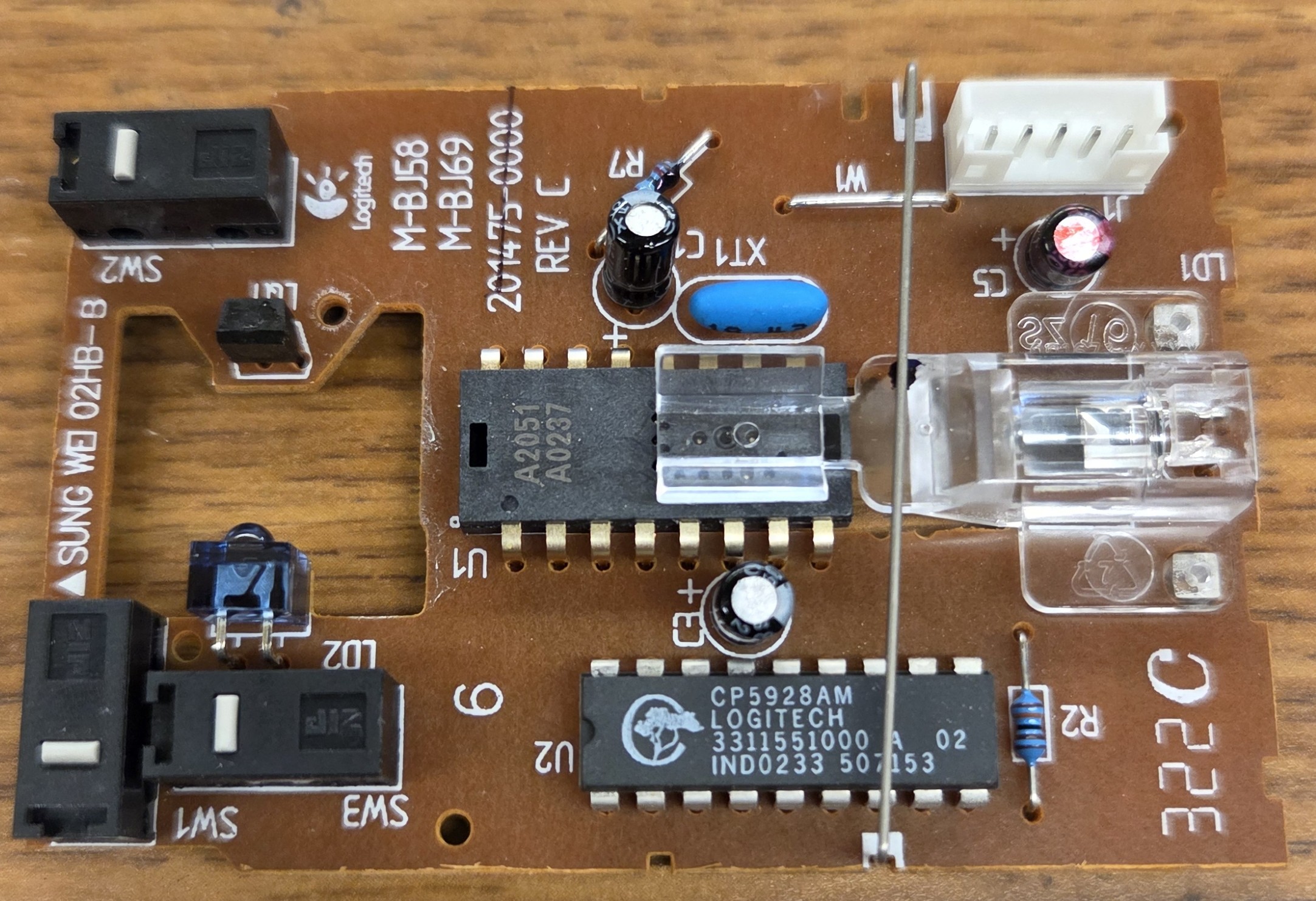
Figure 2. Close-up of the mouse PCB showing the ADNS-2051 chip in the center.
What makes this sensor interesting for imaging is a feature called Pixel Dump mode. When a specific bit is set in the configuration register, instead of computing motion, the sensor streams out the raw pixel values from its internal image array one pixel per frame over the serial port. This is the feature the entire project hinges on.
Hardware Modifications
The first major task was hijacking the necessary pins from the sensor chip to redirect the flow of data. The original mouse had a proprietary Logitech microcontroller that handled USB communication and talked to the sensor over its serial clock (SCLK) and serial data input/output (SDIO) pins. To take control of the sensor with my own microcontroller, I needed to physically disconnect those two pins from the original microcontroller and route them to an ESP32-S3 instead. I desoldered the SCLK and SDIO pins of the ADNS-2051 and attached thin jumper wires to each pin (Figure 3) so they could be routed out to a breadboard for easier prototyping.
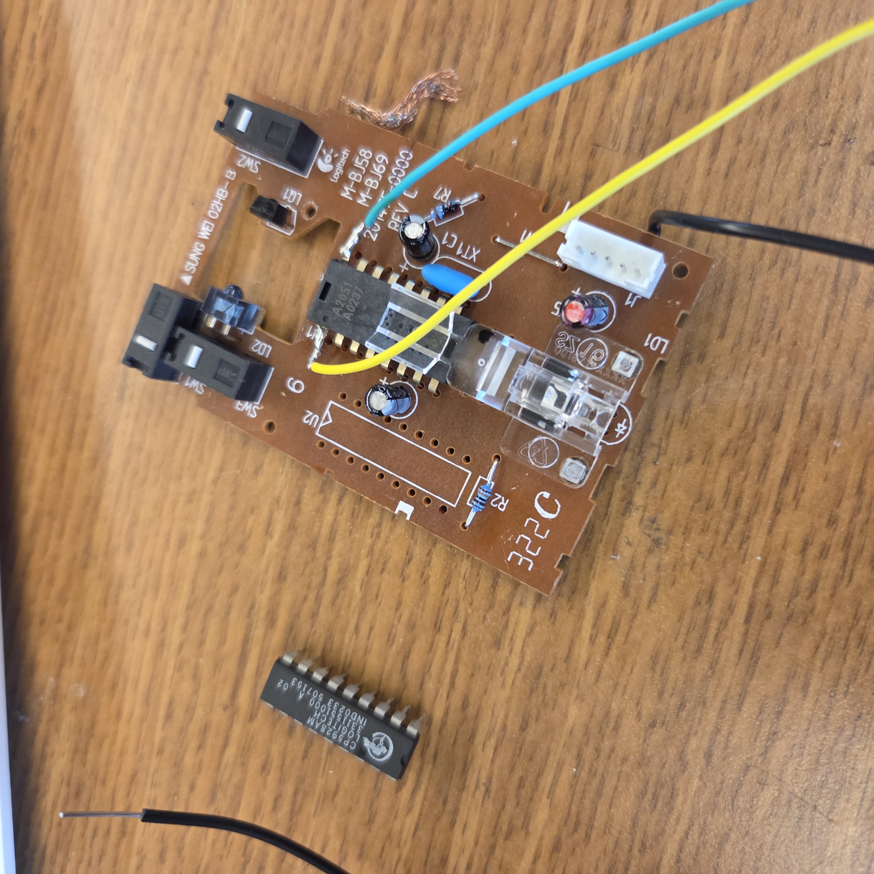
Figure 3. The mouse PCB with the Logitech microcontroller removed and jumper wires soldered to the SCLK and SDIO pins of the ADNS-2051.
However, even with SCLK and SDIO rerouted, the original Logitech microcontroller was still powered and running its firmware, which was controlling other aspects of the sensor, specifically, the sensor's VDD power rail. The ADNS-2051's power was gated through a PNP transistor that the original microcontroller was turning on and off as a power saving feature. With the original microcontroller in an error state because I had cut its sensor communication lines, the sensor's VDD was switching between a low voltages and a few hundred millivolts intermittently, which is not enough to run the chip at all times.
My fix was to remove the original microcontroller entirely (Figure 3) and short across the PNP transistor that was gating sensor power (Figure 4). This permanently connects the sensor's VDD to the USB 5V rail and eliminates all interference from the original firmware. Unfortunately, this does mean that the mouse can no longer function as a mouse, but that is not pertinent for this project.
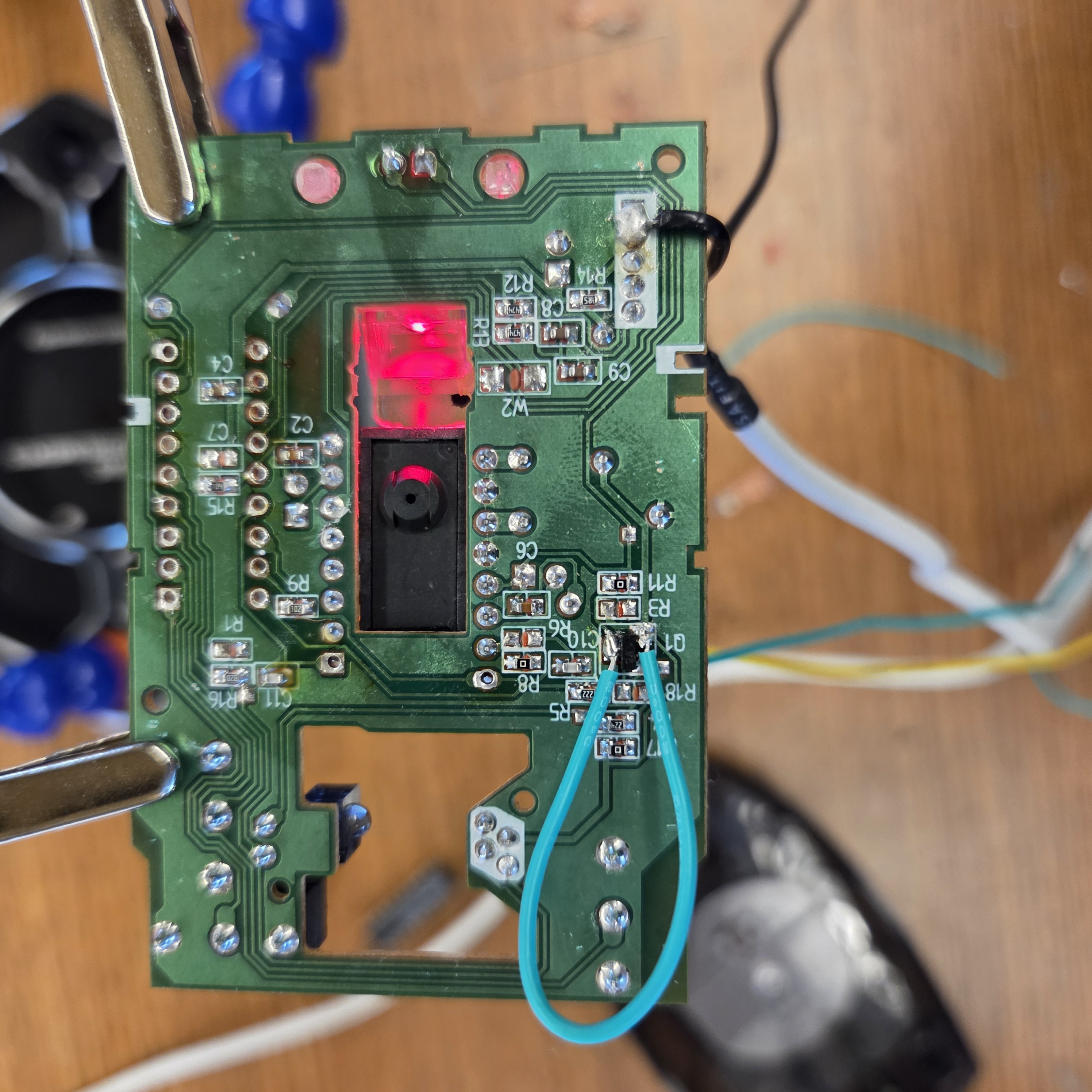
Figure 4. The backside of the mouse PCB showing a wire shorting the emitter and collecter of the PNP transistor to provide 5V directly to the sensor chips VDD.
On the ESP32 side, I used two GPIO pins and the GND pin:
- GPIO1: For sending a controlled clock signal to the sensor chip's SCLK pin.
- GPIO2: For sending or reading serial data in sync with SCLK to the sensor chip's SDIO pin.
- GND: Connected to the ground of the mouse PCB so that it shares a common ground with the ESP32.
The following image shows my prototyping testbench setup.
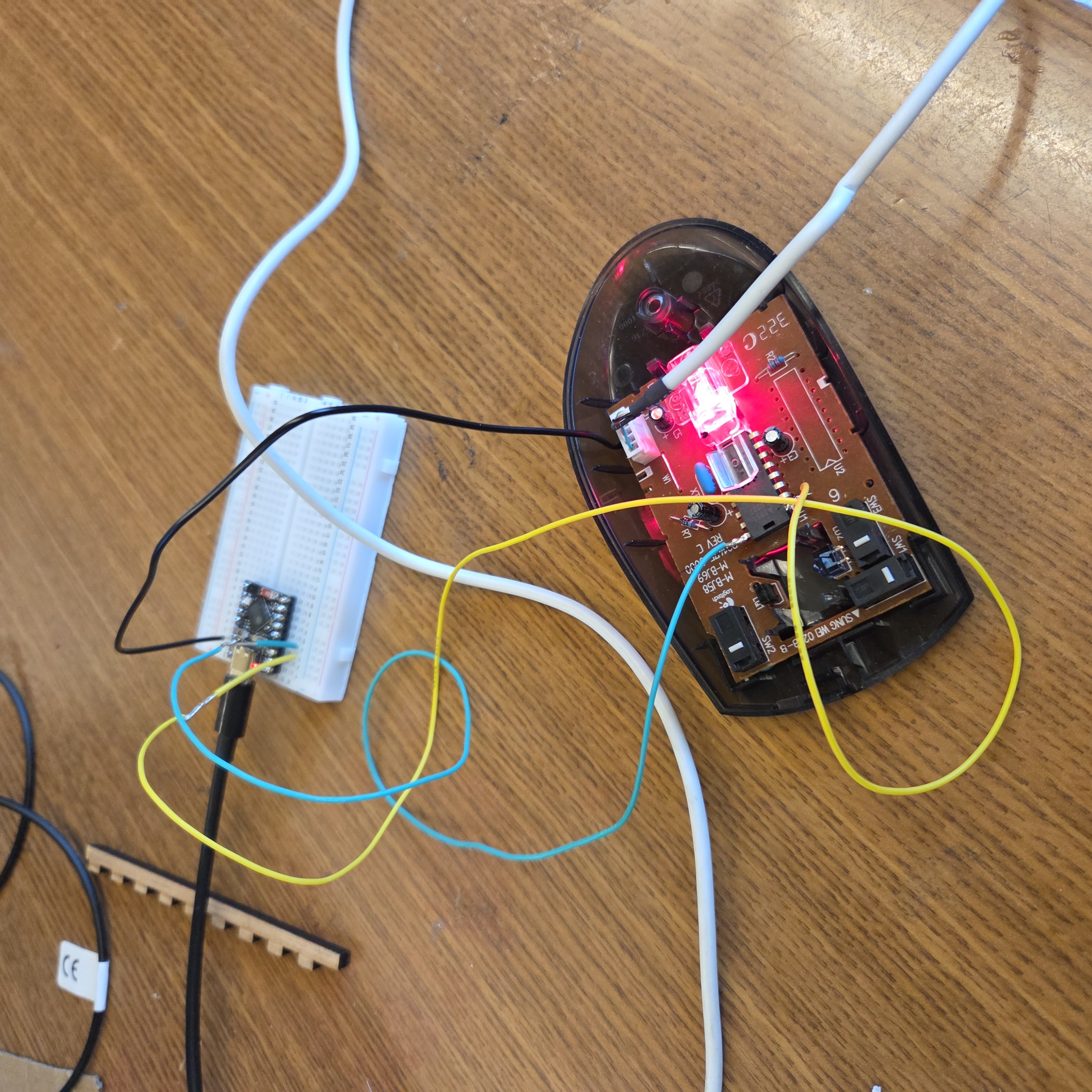
Figure 5. The prototyping setup for testing the hardware.
One subtle concern was that the ADNS-2051 is a 5V chip while the ESP32-S3's GPIOs are 3.3V, which means the sensor's SDIO output high (~5V during reads) technically exceeds the ESP32's maximum GPIO input voltage. In practice, the ESP32's internal clamp diodes absorb the overvoltage at the low currents involved, which is what most hobbyist projects do. A level shifter would be the proper solution, but direct connection has worked without issue for this project, so this would be a consideration for future improvements.
Firmware: Bit-Banging the Serial Protocol
The ADNS-2051 has a non-standard serial protocol. It uses a single shared data line (SDIO) that changes direction based on whether the operation is a read or a write, synchronized by a clock line (SCLK). The MSB of the first byte distinguishes read (0) from write (1), and reads require the microcontroller to pause for at least 100us after sending the address to give the sensor time to prepare its response. Since there's no hardware peripheral on the ESP32 that speaks this protocol, I had to implement it from scratch by manually toggling GPIO pins in software to generate the correct clock and data waveforms with the necessary delays.
The firmware runs two core functions:
reg_write(reg_addr, val)to set sensor configuration registers.reg_read(reg_addr)to retrieve values.
Both functions work by writing directly to ESP32 GPIO registers with microsecond-level timing to meet the sensor's specifications. The toughest part of getting this right was setting the necessary delays so there aren't any setup or hold violations.
Capturing a Full Frame
In pixel dump mode, the ADNS-2051 streams out one pixel per frame (at 1500 frames per second, or ~667μs per pixel). Note that in data dump mode, a frame for the ADNS-2051 is more akin to a clock cycle rather than the entire 256-pixel capture.
According to the data sheet, each pixel is addressed by an 8-bit address and carries a 6-bit brightness value, ranging from 0 (complete black) to 63 (complete white). A validity bit indicates whether the data is ready to be read, and the firmware spins on this bit to ensure it only captures valid pixel data.
The full 256-pixel capture takes about 240ms on my implementation. This is actually close to the theoretical minimum imposed by the sensor itself, which is around 170ms, so the protocol is running near its physical limit.
To view the capture and verify it, I quickly implemented a simple Python script, and Figure 5 below shows a raw 256-pixel capture of the upper half of the letter 'S'.
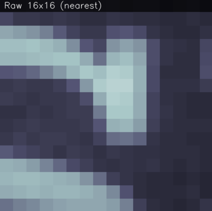
Figure 6. A raw 256-pixel capture of the upper half of the letter 'S', with a slight blue filter to enhance visibility.
Wireless Data Streaming
With pixel capture working over USB serial, the next step was moving the data connection
over WiFi. The ESP32-S3 has built-in 2.4GHz WiFi, so I configured it as a TCP server that
broadcasts captured frames to any connected client. Each frame is serialized as a single
line of comma-separated pixel values prefixed with FRAME: and terminated with a newline,
which makes parsing trivial on the receiving end.
The current setup uses a direct connection where the ESP32 and laptop share a 2.4GHz WiFi network, and the Python viewer connects to the ESP32's IP address on TCP port 8080.
Python Visualization
Once the previous stages have been thoroughly tested, I improved my Python script used during testing to connect to the ESP32 over TCP rather than serial. I also switched to using OpenCV rather than matplotlib for displaying the images as its update loop is too slow for real-time streaming and the display windows were unstable.
The viewer displays two versions of each frame side-by-side:
- A nearest-neighbor upscale that preserves the pixel structure on the left (so you can see the individual 16x16 pixels).
- A bicubic upscale with contrast stretching that makes surface textures much more visible on the right.
A HUD was also added along the bottom to show min/max/mean pixel values, a rolling FPS counter, and current frame count. Keyboard controls let me toggle frame averaging (for noise reduction), save frames to disk, and adjust the averaging window size.
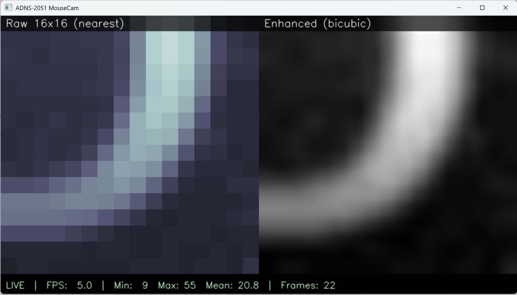
Figure 7. The Python viewer showing the side-by-side raw and enhanced views with the HUD stats bar.
Results
The final system captures live frames from the ADNS-2051 and displays them in real-time on a laptop over WiFi, at roughly 2 frames per second (limited by the sensor's own pixel dump streaming speed). Surface textures are clearly visible: holding the mouse over white paper shows uniform brightness with subtle fiber variations, while moving it over a printed page shows distinct dark regions where text is present. The video below shows the live reading when moving the mouse over the word "multiplexer." Note that it has been sped up by 2 times for the sake of presentation.
Video 1. Sped up live pixel stream from the ADNS-2051, showing the sensor's view change as the mouse is moved across the word "multiplexer."
ECE Skills Gained
- Datasheet reading. The ADNS-2051 datasheet is 40 pages long and full of timing diagrams, register maps, and cryptic sections about serial port synchronization. Becoming fluent in reading datasheets, especially knowing which parts to skim and which parts to read line-by-line, was a skill I gained throughout this project.
- Bit-banged serial protocols. Before this project, I had only used standard hardware peripherals like SPI and I2C. Implementing a custom protocol from scratch, with microsecond-level timing requirements, gave me a much deeper understanding of serial protocols.
- Embedded debugging. Because the ADNS-2051 communicates over a custom bus that can't be monitored by a standard serial terminal, all debugging had to be done through careful incremental testing. Along the way I became comfortable using an oscilloscope to probe the SCLK and SDIO lines when bits weren't coming through correctly.
- Reverse engineering hardware. Tracing PCB signals with a multimeter, identifying the role of each component on the mouse PCB, and deciding what to keep and what to remove was its own kind of engineering puzzle.
- Soldering and desoldering skills. Desoldering fine-pitch pins on a working PCB without damaging surrounding components is not a new skill for me, but this project did give me some much needed practice.
- WiFi and TCP networking on embedded systems. Getting the ESP32 to serve frames over TCP, handling disconnects, and debugging WiFi authentication issues taught me more about the OSI stack than any textbook ever did.
- Real-time image pipelines. Building the end-to-end flow from sensor bits through serialization, network transport, parsing, and OpenCV display gave me experience with pipelines where latency matters.
Final Thoughts
This project pushed me further out of my comfort zone. Going in, I thought the main challenge would be the optics, but in practice the real challenges were reading the dense 40-page datasheet in depth, reverse engineering the mouse PCB with no schematics available, bit-banging a custom serial protocol, and managing power and sync issues across multiple interacting chips. The satisfaction of getting the correct value back from a register after hours of debugging is a feeling I want to chase further, and this project has made me more interested in the embedded and hardware-close-to-silicon side of ECE. If I continue it, the next steps would be adding a proper lens for real imaging, designing a custom PCB that eliminates the hacky wiring, and possibly implementing the "hand-held scanner" idea where the sensor's own motion tracking data is used to stitch frames into a larger image.